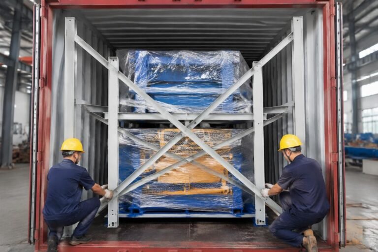

Container Loading for Block Machine 40HQ: QT10-15/QT12-15 Manufacturer Guide
Cramming a container to the brim saves nothing if the forklift cannot reach the molds on arrival.
A proper Container Loading Block Machine 40HQ plan follows the reverse order of on-site assembly, separates hydraulic and electrical zones, and leaves a forklift access lane so the buyer can unload every crate without repositioning the container. I have watched entire QT10-15 lines sit idle for days at West African ports because crates were stacked front-to-back with no aisle, forcing the client to pay for extra container-handling moves just to reach the rear pallets. [NEED_CITE: ISO 18086 guidelines on container cargo securing and unloading access] The goal is never maximum volume—it is minimum on-site rework.
Getting the Container Loading Block Machine 40HQ right starts with understanding that every component has a designated zone, a sequence, and a protection level. Skip any of these, and the buyer pays the price in delayed production, rusted molds, or fried PLC boards.
Why Does Block Machine Loading Need a Dedicated Plan?
A dedicated loading plan prevents mold deformation, electrical moisture damage, and on-site assembly delays that routinely cost buyers more than the freight savings from overstuffing.
When a QT10-15 or QT12-15 line is shipped without a structured plan, three failure patterns appear repeatedly at destination ports. First, molds stacked without spacers develop salt-fog corrosion in the critical gap zones, causing the machine to jam bricks on first startup. Second, the hydraulic station and electrical cabinet are loaded adjacent to each other, and condensation from the hydraulic hoses migrates into the PLC enclosure during tropical sea transit. Third, crates are loaded in random order, meaning the pallet feeder arrives before the main frame, and the client’s crane sits idle. [NEED_CITE: root cause analysis of delayed block plant commissioning in emerging markets]
I once supervised a shipment to a West African capital where the buyer insisted on filling every cubic meter of the 40HQ. The molds were placed on the floor without timber cradles, and the electrical cabinet was sealed with a single layer of stretch film. When the container opened six weeks later, the mold cores had visible rust streaks along the guiding pins, and the PLC display showed moisture condensation inside the enclosure. The client spent the equivalent of a mid-five-figure sum on local machining to restore the mold tolerances—cost several times the savings from that extra half-pallet of spare parts.
A Container Loading Block Machine 40HQ plan is not a packing list. It is a reverse-engineering of the installation sequence, applied to the container’s internal dimensions.
How to Disassemble a Block Machine for Container Shipping?
Disassemble in strict reverse order of assembly, separating the main frame, hydraulic power unit, electrical cabinet, and mold storage into individually labeled zones.
The QT10-15 and QT12-15 machines are designed at the manufacturer’s production facilities with container-compatible joint points. The disassembly sequence follows a fixed logic:
- Remove all molds and pallets first. These are the most dimensionally sensitive components and must be packed in their own zone, away from heavy structural steel.
- Detach the hydraulic power unit from the main frame. Drain the hydraulic oil completely, cap all hose endpoints with plastic seals, and wrap the power unit in moisture-barrier film. [NEED_CITE: hydraulic system preservation standards for long-distance sea freight]
- Separate the electrical cabinet from the machine body. The cabinet travels in a standalone crate, mounted on vibration-dampening rubber pads inside the container.
- Detach the feeder hopper, conveyor brackets, and stacker arms. These bolt back on during installation and travel as sub-assemblies in labeled wooden crates.
- Leave the main frame on its base pallet. The base pallet doubles as the unloading skid at the destination—no additional rigging required.
Each sub-assembly receives a coded label matching the installation manual’s section numbers. A Middle East contractor once received a line where all crates were labeled only with Chinese characters and no installation cross-reference. His local crew spent days matching bolts to holes before realizing the hydraulic manifold crate had been swapped with the color feeder crate.
For the Container Loading Block Machine 40HQ, the main frame always goes in first, positioned against the container’s front wall. The hydraulic unit and electrical cabinet follow, placed side by side in the middle zone with a minimum gap between them. Mold crates and pallet stacks occupy the rear zone, accessible first when the doors open.
How to Pack Molds and Spare Parts for Long-Distance Sea Freight?
Molds require multi-layer rust prevention, timber spacer separation, and a strict stacking limit per container to prevent compression damage during vessel rolling.
Mold protection is the single most neglected area in overseas block machine shipments. The working surfaces of a QT10-15 mold set are machined to tight tolerances, and even minor corrosion along the guide pins or core surfaces will cause brick sticking and uneven wall thickness at startup.
The packing protocol at the manufacturer’s production facilities follows a layered approach:
- Primary layer: All machined surfaces receive a coating of water-displacing corrosion inhibitor, applied by spray and wiped to a thin, even film.
- Secondary layer: Each mold is wrapped in VCI (Vapor Corrosion Inhibitor) paper, sealed at all edges with adhesive tape. [NEED_CITE: VCI packaging effectiveness for ferrous components in marine transit]
- Tertiary layer: Molds are placed on timber cradles with spacer blocks between each unit, preventing metal-to-metal contact. The cradles are bolted to the container floor or secured with lashing straps through designated tie-down points.
A Southeast Asian distributor once ordered a full container of replacement molds for their QT12-15 fleet. The molds were stacked three layers high without intermediate timber spacers—just cardboard sheets between them. After a monsoon-season transit, the bottom layer molds showed compression marks on the core pins, and the cardboard had disintegrated from humidity. The entire bottom layer required re-machining before use.
For a Container Loading Block Machine 40HQ, the recommended mold stacking configuration is two layers maximum for heavy mold sets, with timber cradles rated for the total stack weight. Spare parts—hydraulic seals, guide bushings, sensor cables—are packed in smaller labeled boxes and placed inside the mold crates or in a dedicated spare-parts zone near the container doors for easy access during installation.
What Electrical and Voltage Preparations Must Be Done Before Loading?
The electrical cabinet must be pre-configured for the destination country’s voltage tolerance, sealed against humidity, and wired with labeled terminals before it enters the container.
Voltage instability is the leading cause of PLC and inverter failures in emerging-market block plants. A QT10-15 line shipped to a region with frequent voltage fluctuations will destroy its variable frequency drives within weeks if the cabinet is not pre-configured for wide-tolerance input.
At the manufacturer’s production facilities, every electrical cabinet undergoes a pre-shipment protocol:
- Voltage tolerance configuration. The PLC and VFD parameters are set to accept the destination grid’s voltage range—typically a wide band covering both nominal and fluctuating levels. This is not a software afterthought; it is a hardware-level configuration verified on the test bench before packing.
- Humidity sealing. The cabinet enclosure is sealed with desiccant packs placed inside, and all cable entry points are closed with rubber grommets. The exterior is wrapped in double-layer moisture-barrier film. [NEED_CITE: electrical enclosure IP rating requirements for tropical marine transit]
- Terminal labeling. Every wire terminal receives a printed label matching the installation manual’s wiring diagram. No exceptions. A Latin American buyer once spent days tracing unlabeled wires after a cabinet replacement, because the previous supplier had relied on color coding alone—which faded during transit.
- Spare fuse and relay kit. A sealed bag of replacement fuses, relays, and contactors is attached inside the cabinet door, so the buyer has immediate replacements for the most common field failures.
For the Container Loading Block Machine 40HQ, the electrical cabinet is always loaded in the middle zone, never against the container walls where condensation concentrates. It is secured on vibration-dampening pads and lashed to the floor with straps rated for ocean transit forces.
How to Maximize 40HQ Space Without Blocking Unloading?
Space optimization in a Container Loading Block Machine 40HQ requires weight distribution, a reserved forklift aisle, and lashing points that match the container’s internal tie-down rings.
The internal dimensions of a standard 40HQ container allow for substantial volume, but the usable space for a QT10-15 or QT12-15 line is constrained by weight limits, axle load distribution, and the need for unloading access.
The loading layout follows a fixed sequence:
- Front zone (against container wall): Main frame on its base pallet, centered laterally to balance axle load.
- Middle zone: Hydraulic power unit and electrical cabinet, placed side by side with a gap between them. The hydraulic unit is lashed through its frame tie-down points; the electrical cabinet is lashed through its base skid.
- Rear zone (near container doors): Mold crates and pallet stacks, loaded last so they are the first items accessed when the doors open.
- Forklift aisle: A minimum clearance lane is reserved along one side of the container, from the doors to the middle zone, allowing a standard forklift to extract rear-zone crates without moving front-zone items.
Weight distribution is critical. The main frame is the heaviest single item, and it must be positioned over the container’s central axle group to comply with road transport limits at the destination port. [NEED_CITE: container weight distribution standards for road transport compliance]
A North African contractor once received a Container Loading Block Machine 40HQ where the main frame was loaded against the rear doors, and the mold crates were stacked in the front. The local port authority refused to move the container by road because the rear axle load exceeded the legal limit. The buyer had to pay for on-dock repositioning—a cost several times the original freight.
Every crate is lashed to the container’s internal tie-down rings using ratchet straps rated for the crate’s weight. Wooden braces are wedged between crates and the container walls to prevent lateral shift during vessel rolling. The container doors receive a final safety check: no crate protrudes beyond the door plane, and the locking rods close without obstruction.
Conclusion
A Container Loading Block Machine 40HQ plan is an installation sequence in reverse, not a volume-maximizing exercise. Proper disassembly, mold protection, electrical pre-configuration, and weight-balanced loading with a forklift aisle ensure the buyer can unload, assemble, and start production without costly delays or rework. Every crate labeled, every mold spacer in place, every voltage tolerance set before departure—these are the details that separate a smooth commissioning from a stalled project.